This weekend marks a milestone for the Aquia Line. All major construction and terrain forming is complete. I can put away the chop saw for "good."
| Dave Cooper had the distinction of running the first train from Falmouth to Aquia under the new fully covered mountain. Everything worked as planned....YES! |
| Bayo inspecting the regiment of troops that will be marching through the Potomac Creek Scene |
| Rainer Kurth is a little too tall for my valance panels. |
I had several visitors this weekend. On Saturday Adebayo Adedeji stopped by to check out the layout and see the laser cutter in action. Bayo is a PhD economist who works with me at the CBO. On Sunday Ranier Kurth and Dave Cooper visited. Rainer is an N Scale modeler from Switzerland who frequently travels to the US to see model train events. He is a true "American-o-phile." Back home he drives a 1978 Pontiac Bonneville and models the US railroads on his N scale modules. Dave is a local HO modeler currently working on a urban layout section that he plans to use in a larger layout.
Trying to figure out the best arrangement of the hydraulic feeders to the water wheel is proving a challenge. I am still leaning toward option 2 from the earlier post, in spite of Gerry's vote for option 1. The size of the water wheel will dictate things. The prototype had an overshot wheel, which requires the most vertical drop. Wikipedia says, "Overshot wheels demand exact engineering and significant head, which usually means significant investment in constructing a dam, millpond and waterways. Sometimes the final approach of the water to the wheel is along a lengthy flume or penstock."
I am experiencing this first hand.
Dave Emery's suggestion to use an undershot wheel would solve the problem, but undershot wheels are not appropriate for this locale. A comprise would be to use a breast shot wheel where the water comes in to the wheel at the height of the axle.
 |
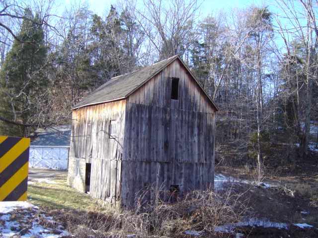
| I learned that this mill is still standing and visible from a public road in Fairfax County. Here is a recent photo. I don't think it was this heavily weathered during the ACW. |

A breast wheel would make sense with your topography. From an engineering perspective, I guess the wheel would need to be wider to make up for the lack of head, but "it's only a model."
ReplyDelete